Lesson 5: Designing with Gears
| Site: | GoLabs |
| Course: | Engineering Design Cycle |
| Book: | Lesson 5: Designing with Gears |
| Printed by: | Guest user |
| Date: | Monday, 22 June 2026, 10:43 PM |
Description
In the final lesson of this unit, students will retrieve a 3d printed "load" using their GoPiGo and their design skills.
1. Investigate: Gears
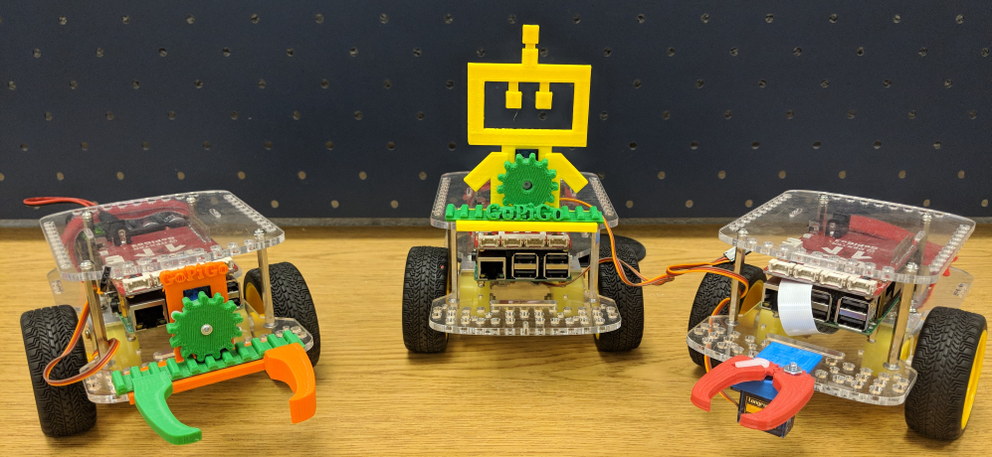
In lesson 4 we attached servo motors to our GoPiGo and had a lot of fun by creating moving parts with the rotating motion of a servo motor. In this lesson, we are going to explore how we can use 3d printed gears to make parts move in different ways. A set of gears working together is a "Gear Drive", where one gear is the driver and pushes the other gear which we call the driven gear.
The two types of gear sets we will explore in this lesson are:
1) Gear Train
2) Rack and Pinion
2. Investigate Gear Train
The first gear set that we will explore is a basic gear train. A gear train is designed by mounting gears on a frame so that the teeth of the gears are aligned. The gears then roll together providing a smooth rotation of both gears. The gear doing the pushing is called the drive gear and the gear that is being pushed is the driven gear.
3. Investigate: Rack and Pinion Gearsets
In this step, we are going to learn how rotary or circular motion can be converted into linear or side to side motion. This will allow us to move parts in a different way. If you have ever used a pulley system, you might consider how the round wheel uses circular motion to move the rope up and down on a linear path. We are going to do the same thing using a rack and pinion gear set. The rack and pinion is comprised of two parts 1) a round gear with teeth called the pinion and 2) a straight bar which also has teeth called the rack. Using a Rack and Pinion is one way to new mechanical parts for your GoPiGo, but it's not the only way.
Attached is a file, that will help you understand the concept of a rack and pinion gear set a bit further. After you print the parts attach them to a servo motor and fit them to the top of your GoPiGo. It is a gear that you can print and attach to a servo motor.
4. Plan: Designing for a Purpose
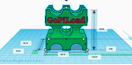
Now it's time to put your design skills to the test! You will design parts and program your robot to pick up a load across a distance. Your teacher will print the attached "GoPiLoad" or item that you will need to retrieve. Use the design process to create GoPiGo parts that will safely return the load across the finish line.
Student Tip:
- Use tape measures or yardsticks to determine how far and in which directions your robot will need to go.
- Design an effective method for moving the Load.
- Upload the GoPiLoad into Tinkercad to help you design parts that can push, pull, or pick the load up.
5. Create
You have all of the tools available now to make the GoPiGo do whatever you like. Consider animal adaptations in the wild as they complete challenges like swimming or climbing a tree. Now spend some time with the engineering design process, your design team, and have fun creating parts for your GoPiGo that will retrieve the GoPiLoad in the most effective way.
6. Evaluate
How successful was your GoPiGo in retrieving the GoPiLoad? We live in a world where autonomous robots do jobs that humans can't or wouldn't want to. How could you relate this challenge to a real-world problem?
How could you relate this challenge to a real-world problem?